According to the regulations of the State Grid, the proportion of distributed generation such as photovoltaics and wind power cannot exceed 10% of the grid, and the energy storage system must be added if it exceeds. Since photovoltaic systems and wind power systems do not use energy storage systems when they are connected to the grid for power generation, it will bring some adverse effects to the power grid. These effects become impossible to ignore. Through the analysis of the characteristics of photovoltaic power generation, it can be seen that the influence of photovoltaic power generation system on the power grid is mainly caused by the instability of photovoltaic power supply. The demand for energy storage systems has increased over the years.
The stable operation of the energy storage system is related to the safety and stability of the power grid, so the major energy storage system manufacturers attach great importance to its quality, and among the factors affecting the stability of the energy storage system, the heat dissipation performance is undoubtedly the most important. Trumony focuses on high-power heat dissipation and has rich experience in the R&D and manufacturing of heat sinks for energy storage systems. Trumony`s thermal management engineers can provide heat dissipation solutions from the beginning of the design of the energy storage system, and can also provide cooling solutions for energy storage systems. The system is optimized for thermal performance. By accumulating rich thermal design data, Trumony can provide accurate thermal simulation and thermal management test data.
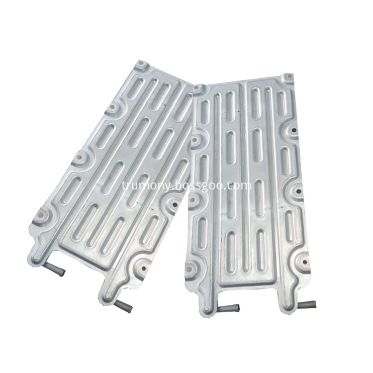
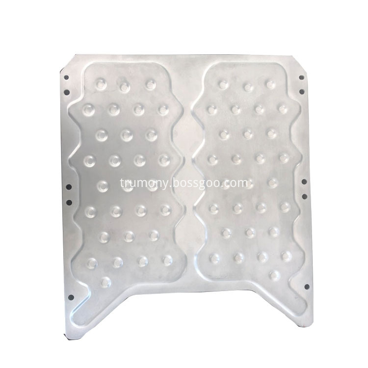
snake tube for ESS,snake tube for energy storage,serpentine tube for battery pack Trumony Aluminum Limited , https://www.szaluminumpipe.com
Product Range
-Valve size:Â
2"Â ~Â 48"Â (DN50-DN1200)
-Pressure:
ANSI Class 150~2500(PN16-PN420)Â
-Temperature:Â
-196ºC~ 500ºC
-Body Materials:
Carbon Steel, Stainless Steel, Alloy Steel, Duplex Steel
-Trim (Disc/Stem):
Carbon Steel, Stainless Steel, Duplex Steel, Alloy Steel
Â
Technical Specifications  Â
-Design: ASME 16.34/ API 6D/ API 600/ BS 1414
-Face to Face: ASME B16.10
-End Flange: ASME B16.5, ASME B16.47
-BW End: ASME B16.25
-Test: API 598/ API 6D/ BS 6755
-Special: NACE MR-01-75
Â
Design Features
-OS & Y, Rising stem
- Bolted Bonnet with spiral-would gasket
-Flexible Wedge
-Backseat Weld-Deposited
-Threaded or welded seat ring
-Renewable seat rings
-Extended Bonnet for Cryogenic Service
-Flanged or butt welded ends.
-By Pass on Request
-Locking Device Optional
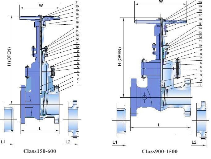
Size and Dimensions:
Class
Dimensions(mm)
NPS(inch)
2
2002/1/2
3
4
5
6
8
10
12
14
16
18
20
24
28
32
40
48
DN(mm)
50
65
80
100
125
150
200
250
300
350
400
450
500
600
700
800
1000
1200
150LB
L
178
190
203
229
254
267
292
330
356
381
406
432
457
508
610
711
813
1067
H
360
490
503
588
740
767
970
1158
1393
1543
1738
1955
2210
2698
2590
2870
3302
3962
W
200
250
250
250
300
300
350
400
450
500
600
650
650
700
800
800
1000
1000
300LB
L
216
241
283
305
381
403
419
457
502
762
838
914
991
1143
1346
1524
1955
2286
H
384
470
528
615
760
800
1005
1212
1455
1585
2035
2195
1680
2200
2641
2857
3713
4501
W
200
250
250
250
350
350
400
450
500
600
650
650
850
850
850
850
750
750
600LB
L
292
330
356
432
508
559
660
787
838
889
991
1092
1194
1397
1549
1778
2149
2667
H
495
550
615
735
826
970
1122
1330
1519
1716
2110
1727
2019
2383
2663
3100
3600
4600
W
250
250
300
350
400
450
500
600
750
850
850
850
850
600
600
750
750
750
900LB
L
368
419
381
457
562
610
727
838
965
1029
1130
1219
1321
1549
-
-
-
-
H
590
700
740
870
950
1078
1318
1580
1860
2004
2178
2362
2463
3048
-
-
-
-
W
250
300
300
350
450
560
640
800
800
900
1000
750
750
900
-
-
-
-
1500LB
L
368
419
470
546
673
705
832
991
1130
1257
1384
1537
1664
1943
-
-
-
-
H
590
700
780
880
1120
1222
1572
1830
2076
2057
2311
2438
2590
2946
-
-
-
-
W
250
350
400
500
600
720
900
900
1000
750
750
850
850
850
-
-
-
-
2500LB
L
451
508
578
673
794
914
1022
1270
1422
-
-
-
-
-
-
-
-
-
H
580
630
765
850
960
1100
1150
1460
1660
-
-
-
-
-
-
-
-
-
W
300
300
300
300
500
500
500
600
600
-
-
-
-
-
-
-
-
-

Â


Model NO.: Z41
Thread Position of Valve Rod: Outside Gate Valve
Usage: Regulation, Safety, Emptying, Drain, Temperature Control, Flow Control
Standard: ANSI
Application: Industrial Usage, Water Industrial Usage, Household Usage
Bonnet: Bolted Bonnet, Pressure Seal, Welded Bonnet
Wedge: Solid, Flexible Wedge;Single Wedge, Double Wedge
Seat: Renewable Seat, Back Seat
Stem: OS&Y, Rising Stem, Non Rising Stem
Cryogenic Service: Extended Bonnet for Cryogenic Services
Design: ASME B16.34, API 600, API 6D, BS1414
Bore: Full Port Design,Regular Bore Design
Connection: Flanged or Butt-Welding End
Operation: Hand Wheel,Bevel Gear,Pneumatic,Electric
Special: by Pass on Request, Nace Mr-0175
Trademark: O. E. M or AEA Brand
Transport Package: Plastic+Wooden Case
Specification: 1500*1500*2000mm
Origin: China
HS Code: 848180
AEAÂ Gate Valve that opens by lifting a round or rectangular gate/wedge out of the path of the fluid. The distinct feature of a gate valve is the sealing surfaces between the gate and seats are planar. The gate faces can form a wedge shape or they can be parallel. Typical gate valves should never be used for regulating flow, unless they are specifically designed for that purpose. On opening the gate valve, the flow path is enlarged in a highly nonlinear manner with respect to percent of opening.